
concept
Creo Advanced Assembly (AAX): Skeleton Models & Interface Management
How skeleton models and interfaces help manage component relationships in large Creo assemblies.
As Creo assemblies grow, managing the relationships between components becomes increasingly important.
Components may need to maintain mounting locations, connection points, clearances, routing interfaces, and other design relationships while the overall product continues to change. If these relationships are created directly between many individual components, an assembly can quickly become difficult to understand and maintain.
Creo Advanced Assembly Extension (AAX) provides tools for managing these relationships using a top-down design methodology, including skeleton models, Publish Geometry, Copy Geometry, Shrinkwrap, and external-reference controls.
Table of Contents
Interface Management Fundamentals
Why Interface Management Matters
Every component in an assembly interacts with other portions of the design.
For example, a piece of equipment may have:
Mounting locations
Electrical connectors
Piping or cabling interfaces
Required clearance volumes
Service-access requirements
Interfaces with surrounding structure
As the design develops, these interfaces may move or change.
A supplier component may be replaced. A frame may become larger. A connector may move. A subsystem may be relocated to another portion of the assembly.
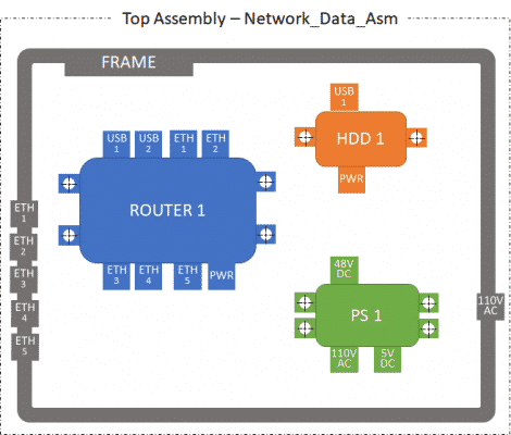
Example of a larger assembly containing several components with shared mounting, power, data, and structural interfaces.
In real-world designs, the challenge becomes even greater because different subassemblies are often owned by different engineers, teams, or external suppliers.
The challenge is therefore not simply making the assembly look correct. It is controlling what each model depends on and how design information is shared so that changes can be made without creating unnecessary failures throughout the assembly.
External References
An external reference is created when a feature in one model depends on geometry or information from another model.
For example, imagine two separate subassemblies beneath the same top-level assembly. If a component inside one subassembly directly references a surface, edge, datum, or other feature from a component in the other subassembly, Creo must maintain that dependency between the two branches of the assembly structure.
External references are not inherently bad. Complex products naturally require models to depend on information from other models.
Problems arise when those dependencies are created without a deliberate reference strategy.
Uncontrolled external references can make it more difficult to:
Replace components
Reorganize an assembly
Divide work between teams
Determine why a model has failed
Work independently from unrelated portions of an assembly
Predict how a design change will propagate
Depending on the reference structure and Creo configuration, Creo may also need to retrieve additional referenced models or portions of the assembly hierarchy to resolve these dependencies. In very large assemblies, poorly controlled references can therefore affect retrieval and regeneration performance.
AAX provides tools such as skeleton models, Publish Geometry, Copy Geometry, and External Reference Control to make these relationships more intentional.
Skeleton Models
What Is a Skeleton Model?
A skeleton model is a special Creo model used to capture and distribute important design information within an assembly.
Rather than representing a manufactured component, the skeleton serves as a design framework for the assembly.
A skeleton may contain information such as:
Coordinate systems
Datum planes, axes, and points
Curves and sketches
Surfaces
Equipment envelopes and space claims
Mounting locations
Connector and interface locations
Routing references
Copy Geometry features
Other geometry used to communicate design intent
Instead of allowing every component to depend directly on every other component, a skeleton provides a controlled source of shared design information.
A simplified relationship can be thought of as:
System-Level Design Intent
↓
Skeleton Model
↓
Subassemblies and Components
PTC describes skeleton models as a central location for design criteria that can then be distributed throughout the product structure.
Why Use Skeleton Models?
Skeleton models provide several important advantages when managing larger assemblies.
Communicate Design Intent
A skeleton can define important system-level requirements before the detailed components are complete.
Changes to those requirements can then be propagated to the models that depend on them.
Keep Shared Information Lightweight
A skeleton does not need to contain the complete detailed geometry of every component.
Instead, it can contain only the surfaces, datums, curves, space claims, and interfaces that downstream designers actually require.
This can allow assembly-level work such as routing, packaging, and interface design to continue without requiring every detailed component to be loaded into the Creo session.
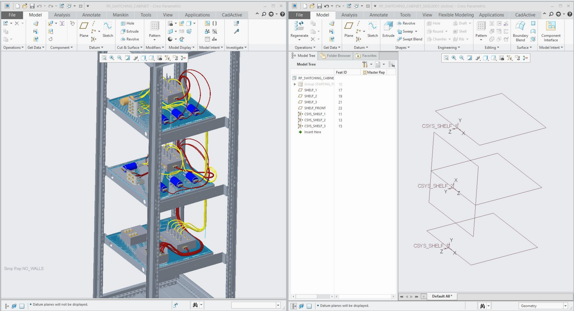
The detailed assembly and its lightweight skeleton representation.
Provide a Clear Reference Structure
Rather than creating ad-hoc component-to-component references, organizations can establish a predictable path for sharing design information through skeleton models and controlled data-sharing features.
What Can a Skeleton Contain?
Skeleton geometry generally falls into two broad categories.
Standalone Geometry
Standalone geometry is created directly inside the skeleton.
This might include:
Coordinate systems
Datum planes
Datum axes
Datum points
Curves and sketches
Surfaces
Standalone geometry is particularly useful in a true top-down workflow because the design criteria originate in the skeleton and can then drive downstream models.
Shared or Copied Geometry
A skeleton can also contain representations of geometry originating in other models.
This is commonly accomplished using:
Copy Geometry
External Copy Geometry
Shrinkwrap
These tools allow the skeleton to represent important geometry without reproducing an entire detailed component.
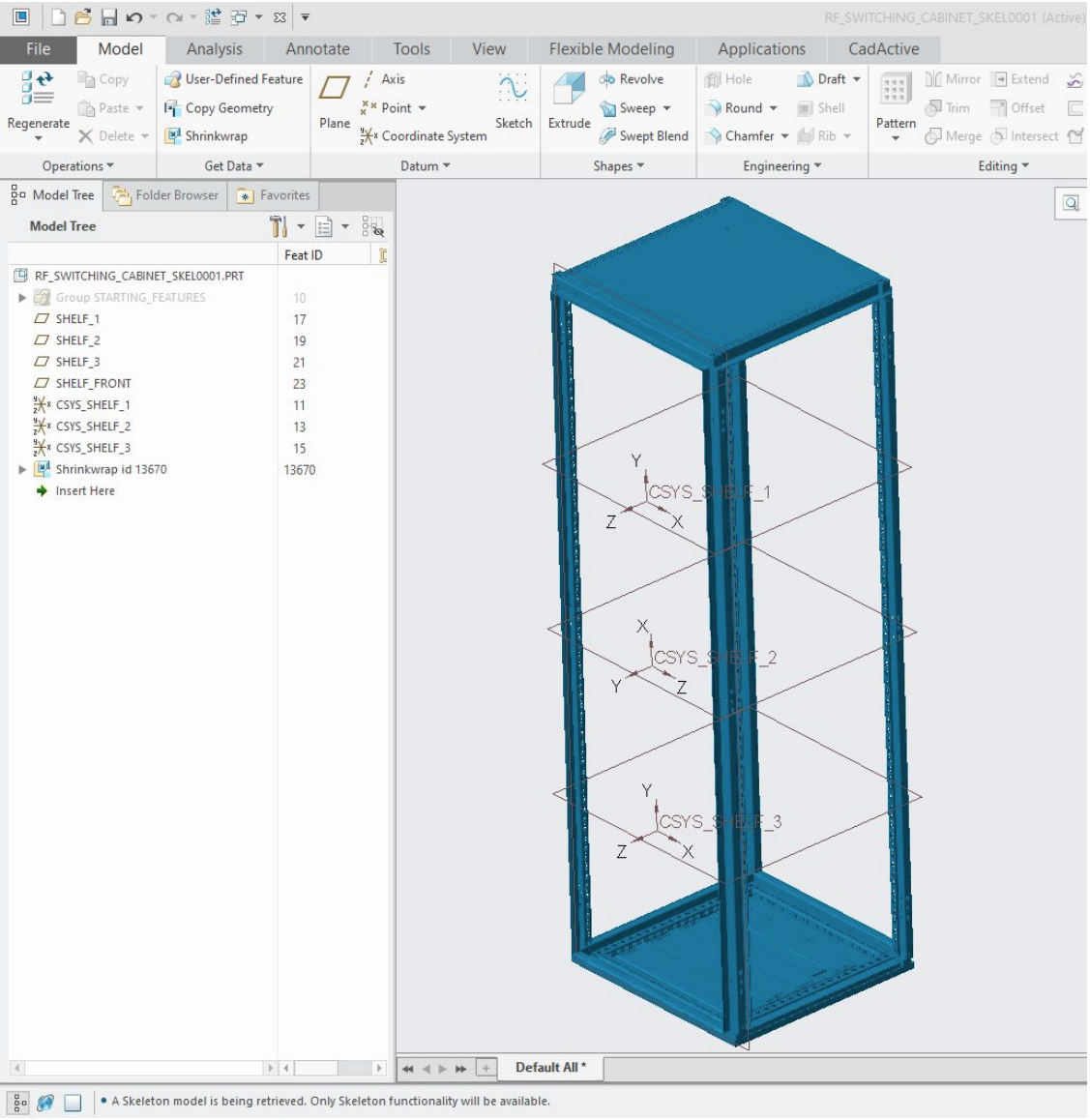
Example skeleton containing both datum references and surface geometry.
Top-Down Design
Skeleton models are strongly associated with top-down design.
In a traditional bottom-up workflow, individual components are designed first and later assembled together.
With top-down design, important product-level requirements and relationships are established first and then distributed downward to the teams and models responsible for the detailed design.
A simplified workflow is:
Establish the product and assembly structure.
Identify important interfaces and design criteria.
Capture those requirements in the appropriate skeleton model.
Distribute the required information to lower-level skeletons or components.
Develop the detailed components using those controlled references.
This provides a clear direction for design information:
Top-Level Requirements
↓
Top-Level Skeleton
↓
Subsystem Skeletons
↓
Detailed Components
PTC recommends this direction for true top-down design because it creates a clear hierarchy of driving design criteria.
Individual teams can then develop their portions of the product while remaining aligned with the system-level requirements maintained above them.
Publish Geometry and Copy Geometry
Two of the most important AAX tools used to manage shared geometry are Publish Geometry and Copy Geometry.
Publish Geometry
A Publish Geometry feature identifies a controlled group of local geometry that another model is intended to reference.
For example, a component or skeleton owner may publish:
Mounting coordinate systems
Connector locations
Mounting surfaces
Interface curves
Datum points
Other intentional design interfaces
A useful way to think about Publish Geometry is:
“This is the geometry I intend other models to use.”
The Publish Geometry feature itself does not create a second copy of the selected geometry. It organizes and identifies local references so they can be consumed in a more controlled way by other models.
This is preferable to requiring downstream designers to search through an entire source model and decide for themselves which geometry should be referenced.
Consistent Publish Geometry features also make the intended interfaces easier to identify, name, and maintain.
Copy Geometry
A Copy Geometry feature brings selected design information from another model into the active model.
Depending on the source data, Copy Geometry can be used to share information such as:
Surfaces
Datums
Curves
Other reference geometry and properties
In a top-down workflow, Copy Geometry is commonly used to distribute design intent from a higher-level skeleton into lower-level skeletons and components.
For example:
Top-Level Skeleton
↓
Copy Geometry
↓
Subsystem Skeleton
↓
Copy Geometry
↓
Detailed Component
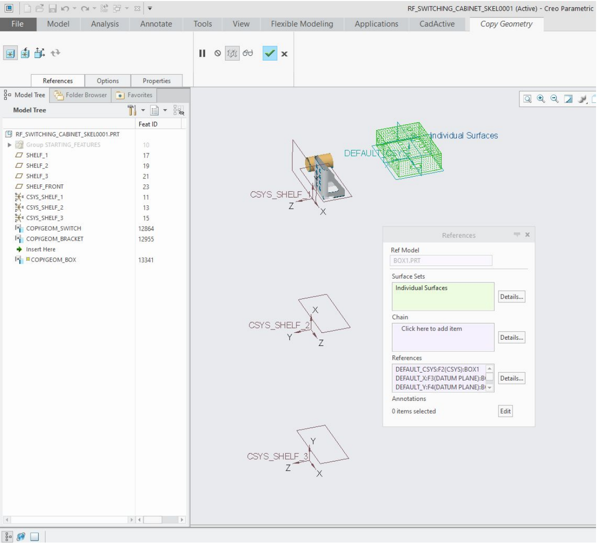
Example of Copy Geometry bringing selected interface information from another model into a skeleton.
Publish Geometry and Copy Geometry Together
Publish Geometry and Copy Geometry work particularly well as a pair:
Source Model
→ Publish Geometry
→ Copy Geometry
→ Target Model
The source model identifies the information that is intentionally available for sharing, while the target model consumes that information through Copy Geometry.
This creates a more understandable reference structure than allowing arbitrary geometry to be selected throughout an assembly.
Internal and External Copy Geometry
Creo supports both local/internal and external Copy Geometry workflows.
Understanding the difference is particularly useful when managing large assembly structures.
Internal Copy Geometry
A local or internal Copy Geometry feature is created within the context of an assembly.
Creo can use the assembly hierarchy and relative placement of the source and target models to establish the relationship between them.
This can be appropriate when the assembly context itself is an intentional part of the design relationship.
However, that also means the reference may depend on portions of the assembly hierarchy between the source and target models.
In very large assemblies, this is one reason organizations may prefer external Copy Geometry for certain shared interfaces.
External Copy Geometry
An External Copy Geometry feature references geometry from another model without relying on the assembly path between the two models.
This can reduce unnecessary assembly-context dependencies while still allowing the target model to receive the required design information.
Important: External Copy Geometry does not automatically mean the geometry is frozen or disconnected from its source.
Depending on the update configuration, an external Copy Geometry feature can remain associative with the source and can:
Update automatically
Be updated manually
Notify the user when the source changes
Have its dependency intentionally removed
If the dependency is intentionally removed, the copied geometry becomes independent and will no longer follow changes to the original source.
A local Copy Geometry feature can also be converted to External Copy Geometry. This conversion is one-way; an external feature cannot later be converted back to the original internal Copy Geometry type.
When converting geometry to external, Creo provides placement methods such as Default, Current Placement, and Coordinate System to establish how the source geometry is positioned in the target model.
Two Common Skeleton Workflows
Not every assembly begins as a completely new top-down design. In practice, skeleton models are often used in two different situations.
Design-Driving Skeletons
For a new top-down design, the preferred approach is to establish the important design criteria in the skeleton first.
The skeleton may define:
Equipment locations
Mounting points
Structural envelopes
Interface locations
Connection points
Routing boundaries
Space claims
Those requirements are then distributed downward to the detailed models.
This gives the skeleton clear ownership of the system-level design intent.
Working with Existing or Supplier Components
In other situations, the detailed component already exists and contains an interface that the rest of the assembly needs.
Examples include:
Purchased equipment
Supplier models
Existing company designs
Legacy components
Bottom-up assemblies being integrated into a larger system
In these situations, important interface geometry may be published from the existing component and copied into a skeleton so other designers can work from a controlled representation of that interface.
This is the workflow illustrated in the original Skeleton Model Basics documentation.
PTC notes that copying detailed part geometry upward into a skeleton is not the preferred direction for a true top-down methodology because it introduces a dependency from the skeleton back to the detailed component.
However, it can be entirely practical when existing or supplier geometry must be incorporated into the design.
The important part is understanding the dependency and creating it intentionally.
Shrinkwrap Features
A Shrinkwrap provides another method for representing existing model geometry in a lightweight form.
Rather than sharing only a small number of individual interfaces, a Shrinkwrap can provide a simplified representation of a larger part or assembly.
This can be useful when a skeleton needs to represent:
Surrounding equipment
Packaging envelopes
Larger groups of components
Simplified exterior geometry
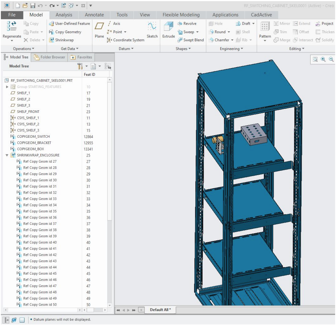
Example of Shrinkwrap geometry representing multiple assembly components inside a skeleton.
Shrinkwrap can be a powerful tool, but it should be used selectively.
If a downstream designer only needs a handful of mounting points, connector locations, or interface surfaces, a small set of Publish Geometry and Copy Geometry features will generally communicate the design intent more clearly.
Large Shrinkwrap features can contain much more information than the downstream designer actually needs and can become more difficult to troubleshoot if references change.
Managing Design Changes
Design iteration is unavoidable.
During development:
A component may change size
A connector may move
Equipment may be relocated
A mounting location may change
A component may be replaced entirely
Additional interfaces may be introduced
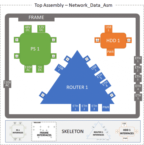
Example of design changes that require the shared skeleton interfaces to be updated.
When design information is managed through skeleton models and controlled data-sharing features, those changes can propagate through a more understandable reference structure.
For example:
System Requirement Changes
↓
Skeleton Updates
↓
Shared Geometry Updates
↓
Dependent Components Update
Exactly how those changes propagate depends on the data-sharing feature and its update settings.
Some shared geometry may update automatically. Other geometry may be configured for manual update or notification. In some situations, the dependency may intentionally be removed.
The goal is not to eliminate dependencies.
The goal is to make those dependencies intentional, understandable, and maintainable.
External Reference Control
AAX also provides tools for controlling which external references users are allowed to create.
For example, an organization can configure Creo so that designers are limited to referencing:
Skeleton models
Models within the same subassembly
Published Geometry
Other explicitly permitted references
Creo can also restrict external geometry selection so that only Publish Geometry is available from a source model.
These controls can help prevent accidental component-to-component relationships from being introduced simply because a designer happened to select convenient geometry on the screen.
Best Practice: Before creating an external reference, consider whether the selected geometry represents an intentional and stable design interface.
For CAD administrators, Creo's External Reference Control settings can be an important part of enforcing a consistent assembly-management methodology across an organization.
Working with Populated Skeleton Models
Once a skeleton contains many interfaces, coordinate systems, surfaces, curves, and Copy Geometry features, navigating the model can become difficult.
Creo provides several built-in tools that can help.
Datum Display
Hide datum types that are not relevant to the work you are currently doing.
For example, if you are looking for coordinate systems, temporarily hiding datum planes, axes, and points can make a populated skeleton much easier to understand.
The goal is simply to reduce unnecessary visual clutter while working with the skeleton.
Zoom to Selected
When you identify a feature in the Model Tree, Zoom to Selected can quickly locate the associated geometry in the graphics window.
This is especially useful for surfaces and standalone datum features.
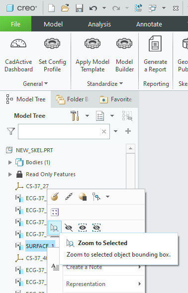
Using Zoom to Selected to locate a skeleton feature in the Creo graphics window.
Copied geometry can sometimes be more difficult to identify visually than standalone features. When a recognizable placement coordinate system or other datum is available, locating that reference first can make the associated shared geometry easier to understand.
Creo Search Tool
Creo's built-in Search Tool is particularly useful when working with a large skeleton.
Press:
CTRL + F
to open the Search Tool.
You can search for specific feature types, names, and other criteria rather than manually expanding and inspecting a large Model Tree.

Creo's Search Tool can help locate specific features within a heavily populated skeleton.
Consistent feature naming becomes extremely valuable here.
A skeleton with meaningful names for interfaces, coordinate systems, Publish Geometry, and Copy Geometry features is much easier to navigate than one containing hundreds of generically named features.
Skeleton Modeling Best Practices
There is no single skeleton structure that is correct for every product, but several practices can make skeleton-based designs significantly easier to maintain.
Keep Skeletons Focused
A skeleton should contain important shared design information, not every piece of geometry available in the assembly.
Only distribute the information downstream designers actually need.
Prefer a Clear Top-Down Dependency Structure
For new designs, allow high-level skeletons to drive lower-level skeletons and detailed components whenever practical.
Avoid unnecessary circular references or situations where top-level design criteria accidentally depend on detailed downstream components.
Use Publish Geometry for Intended Interfaces
When geometry is intentionally meant to be consumed by other models, define it with Publish Geometry rather than requiring users to select arbitrary source geometry.
Creo can also be configured so Publish Geometry is the preferred or required reference method.
Name Important Features
Use meaningful names for:
Publish Geometry
Copy Geometry
External Copy Geometry
Coordinate systems
Interface datums
Curves and surfaces
Good naming communicates design intent and makes Creo's Search Tool much more useful.
Choose Copy Geometry Dependencies Intentionally
Use associative shared geometry when downstream models are expected to follow changes to the source.
Use manual, notification, or no-dependency behavior only when it matches the design-management requirements of the organization.
Do not remove a dependency simply for convenience if downstream models are expected to remain synchronized.
Use External Copy Geometry Where Appropriate
External Copy Geometry can reduce dependency on the assembly hierarchy between source and target models.
This can be particularly helpful for large assemblies, but it should still be implemented using a deliberate reference and update strategy.
Use Shrinkwrap Selectively
Shrinkwrap is useful when a broader simplified representation is required.
When only a few interfaces are needed, individual Publish Geometry and Copy Geometry features are generally easier to understand and maintain than a large Shrinkwrap.
Keep Stable Information Early
Place relatively stable skeleton information early in the Model Tree and more dynamic information later.
Changes to shared-data features can cause downstream dependent features to regenerate, so thoughtful feature organization can improve both model stability and regeneration behavior.
Use Reference Controls
CAD administrators should consider configuring Creo's External Reference Control settings to reinforce the organization's intended assembly-management methodology.
For example, reference selection can be restricted to skeleton models or Publish Geometry when appropriate.
How CadActive Can Help
Building and maintaining skeleton models manually can require significant effort, particularly when large numbers of interfaces need to be published, copied, renamed, or updated as the assembly changes.
CadActive Skeletons provides tools designed to streamline many of these workflows while still using Creo's native skeleton, Publish Geometry, and Copy Geometry functionality.
CadActive can help automate tasks such as:
Creating consistently named Publish Geometry features
Creating multiple Copy Geometry / External Copy Geometry features in bulk
Applying organization-defined naming and reference standards
Updating copied geometry when component placement changes
Re-parenting skeleton references as the assembly structure evolves
Managing and navigating large skeleton-model workflows
The goal is not to replace Creo's AAX methodology, but to make established skeleton-modeling practices easier to apply consistently across larger teams and assemblies.
When Should Skeleton Models Be Used?
Skeleton models are particularly useful when:
Multiple teams are working concurrently on a product
System-level design intent must be distributed to many components
Assembly interfaces change frequently
Components need to be replaced without breaking unrelated models
Piping, cabling, or harness design requires stable interface locations
Purchased or supplier components must be integrated into a larger system
Large assemblies contain complex external-reference relationships
Designers need to work from lightweight interface information rather than complete detailed models
Skeleton models may be unnecessary for very small assemblies with only a few simple relationships.
The objective is not to use skeletons simply because the functionality exists.
The objective is to use them where they provide a clearer and more controlled way to communicate design intent and shared interfaces.
Creo Advanced Assembly Extension (AAX)
The functionality described in this article is closely associated with the Creo Advanced Assembly Extension (AAX).
PTC describes AAX as providing capabilities for:
Top-down and concurrent design
Skeleton models
Design-intent distribution
Reference and dependency management
Associative data sharing
Change propagation through complex assembly structures
If the advanced assembly or shared-data functionality expected by your organization is unavailable, verify that the appropriate Creo Advanced Assembly license is available and being obtained by Creo.
Additional PTC Documentation
For more information on the concepts covered in this article, refer to the following PTC resources:
PTC – Creo Advanced Assembly Extension Package
PTC Help – About Skeleton Models in Top-Down Design
PTC Help – Assembly Functionality and Skeleton Models
PTC Help – Copying Geometry in Top-Down Design Methodology
PTC Help – About Publish Geometry Features