
howto
Controlling Fiber Color with Datasets in Creo Schematics
How to make a fiber's displayed color change automatically based on the selected dataset in Creo Schematics.
When working with fiber datatables in Creo Schematics, you may want the displayed color of a fiber to change automatically depending on which dataset is selected.
For example, a wire datatable may contain different rows for wire gauge, part number, insulation, or color. While a COLOR parameter can contain important information about the physical wire and downstream Cabling data, it does not necessarily control how that fiber is graphically displayed in Creo Schematics.
To control the visible fiber color from a dataset, a useful approach is to use Creo Schematics layers.
How It Works
The basic workflow is:
Create Layers
↓
Assign a Color to Each Layer
↓
Add the Layer to Your Fiber Datasets
↓
Apply a Dataset to the Fiber
When the dataset changes the fiber's assigned layer, Creo Schematics can display the fiber using the color configured for that layer.
This allows the graphical color of a fiber to follow the dataset selected by the designer.
1. Create the Required Layers
In your Creo Schematics design, open:
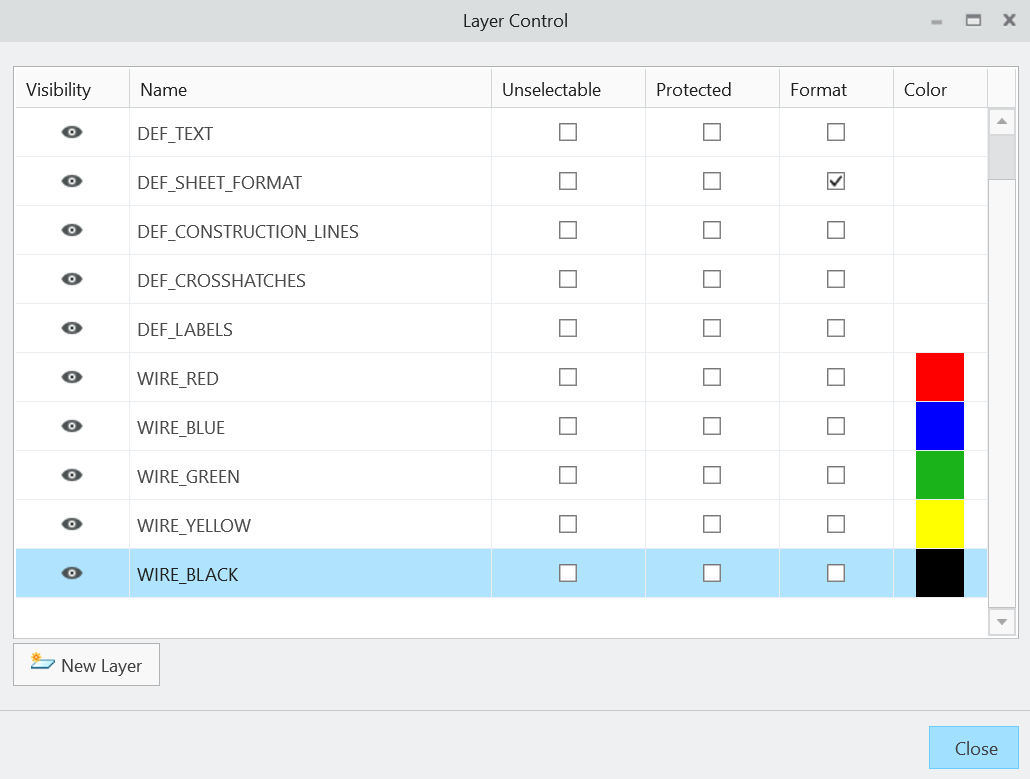
View → Layer Control
Create the layers you want to use for your different fiber colors.
For example:
WIRE_REDWIRE_BLUEWIRE_GREENWIRE_YELLOWWIRE_BLACK
Select each layer and assign the desired color.
Tip: Use descriptive layer names rather than simply
RED,BLUE, etc. This can make the purpose of the layers easier to understand in larger designs.
2. Enable Layer Colors
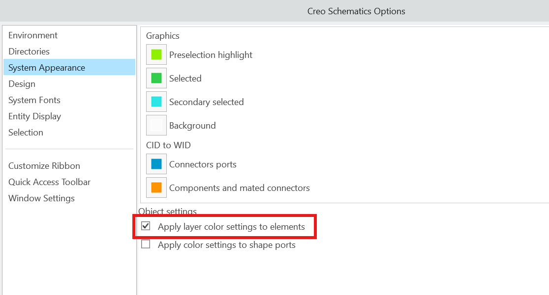
For the assigned layer colors to control the appearance of the fibers, open:
File → Options → System Appearance
Enable:
Apply layer color settings to elements
With this setting enabled, the color assigned to a layer can override the individual graphical color of objects placed on that layer.
3. Add the Layer to the Fiber Datatable
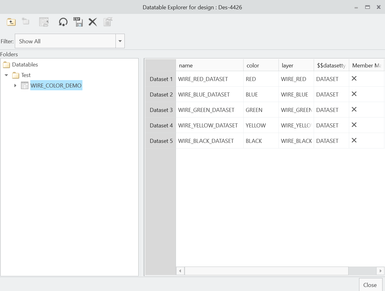
Next, add the Creo Schematics layer parameter to the datatable used by your fiber.
Each dataset should contain the layer that corresponds to the desired graphical color.
For example:
Gauge | COLOR | layer |
|---|---|---|
16 | RED | WIRE_RED |
16 | BLUE | WIRE_BLUE |
18 | GREEN | WIRE_GREEN |
18 | YELLOW | WIRE_YELLOW |
The COLOR value can continue to describe the actual wire color for downstream use, while the layer value controls which Creo Schematics layer the fiber is assigned to.
The value in the layer column must correspond to a layer that exists in the Creo Schematics design.
4. Apply the Dataset to the Fiber
Once the layers and datatable have been configured:
Select a fiber in the design.
Open the fiber's Properties or use the embedded parameters area.
Select Apply Dataset.
Choose the desired dataset.
Apply the selection.
When the dataset is applied, its parameters are transferred to the fiber. The fiber is moved to the layer specified by the dataset, and the configured layer color is displayed.
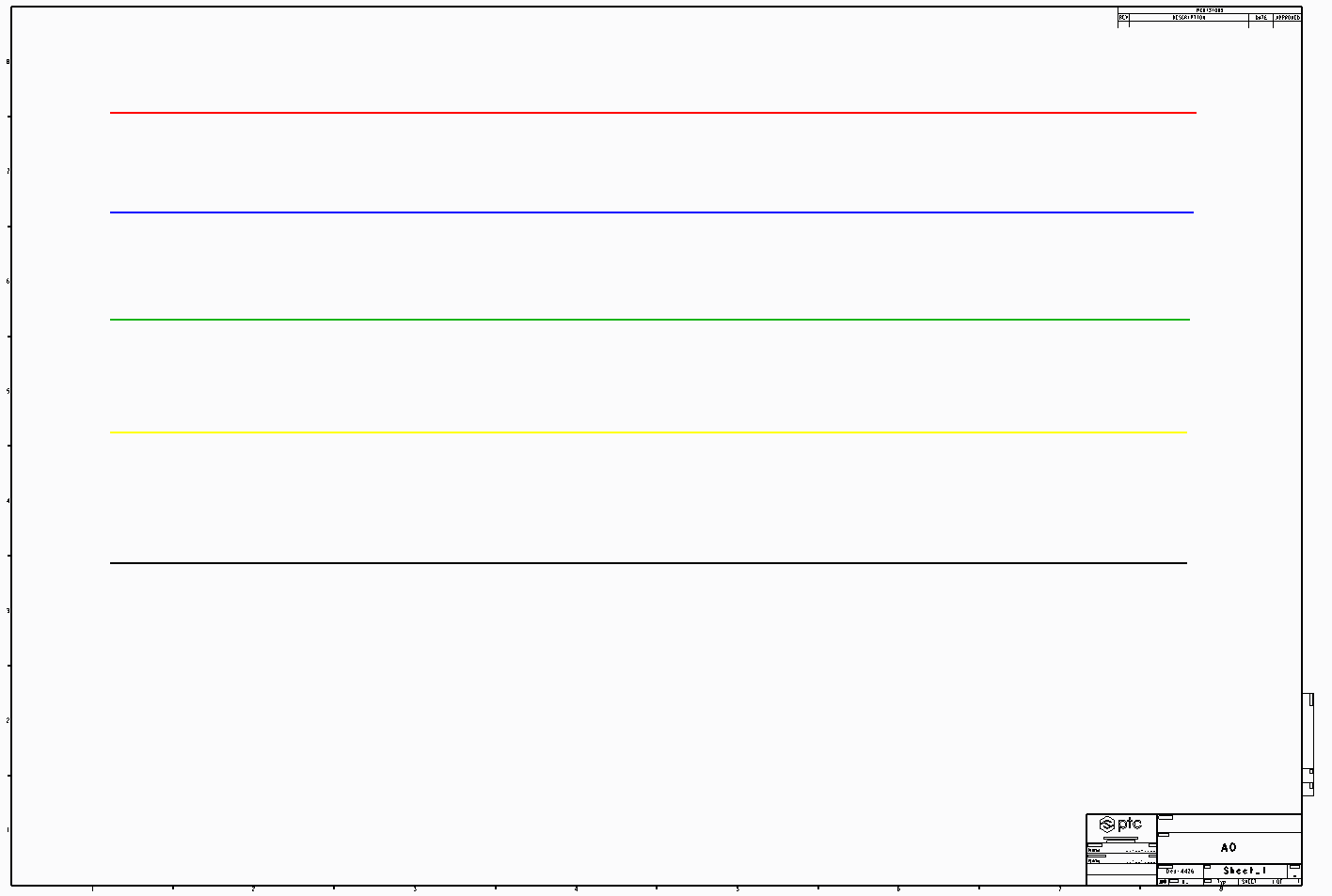
For example, selecting a dataset containing:
layer = WIRE_RED
will place the fiber on the WIRE_RED layer and display it using that layer's configured color.
Selecting another dataset containing:
layer = WIRE_BLUE
will move the fiber to WIRE_BLUE and update its displayed color accordingly.
COLOR vs. Display Color
It is useful to keep these two concepts separate:
COLORparameter — Data describing the physical color of the wire and commonly used as part of the downstream Cabling information.Fiber display color — The graphical color shown on the Creo Schematics sheet.
Using the layer parameter allows the two to work together without relying on the COLOR parameter itself to control the graphical appearance.
Tip: If the fiber changes layers correctly but does not visually change color, verify that Apply layer color settings to elements is enabled under File → Options → System Appearance.