
howto
Configuring Fitting Category Icons in Creo Spec-Driven Piping
How to control the fitting-category icons Creo shows when inserting fittings in Spec-Driven Piping.
When inserting fittings in Creo Spec-Driven Piping, Creo displays a set of fitting-category icons for common component types such as valves, flanges, elbows, branches, reducers, and supports.
These buttons are controlled by the Fitting Category Map file, which determines:
Which fitting-category buttons are displayed
The order in which the buttons appear
Which icon is displayed for each button
Which fitting categories are grouped beneath each icon
Whether a valve number is required for the category
This allows CAD administrators to customize the fitting-selection interface to better match the piping components used by their organization.
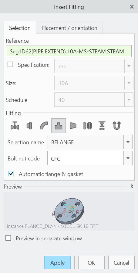
Example fitting-category buttons displayed while inserting a fitting in Spec-Driven Piping.
The Fitting Category Map File
The default Fitting Category Map file is:
piping_fitt_category_map.csv
For PTC's sample Spec-Driven Piping project, it can typically be found at:
<Creo Load Point>\Common Files\text\piping_data\sample_project\piping_fitt_category_map.csv
If your organization maintains its own Spec-Driven Piping project data, the file should instead reside with the project data identified by your Creo piping configuration.
The configuration option:
piping_fitt_category_map_file
identifies the Fitting Category Map file Creo should use.
PTC requires this file to be stored in the project-data directory specified by:
piping_project_data_dir
Understanding the Map File
The Fitting Category Map contains four primary fields:
Field | Purpose |
|---|---|
| Controls the order in which fitting-category buttons appear |
| Identifies the icon file displayed for the category |
| Identifies the fitting category or categories associated with the button |
| Determines whether a valve number is required |
A typical file may contain entries similar to:
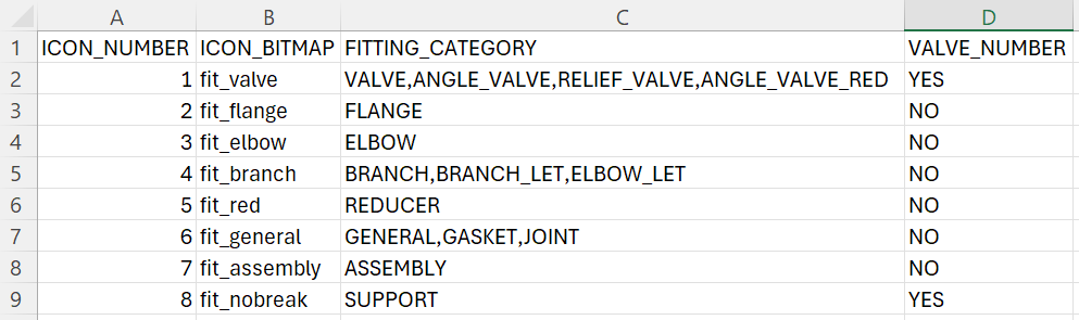
ICON_NUMBER
ICON_NUMBER determines the order of the category buttons in the fitting-selection dialog.
Creo displays the icons from left to right beginning with:
1
If a large number of category icons are configured, Creo provides scrolling within the fitting-selection area.
ICON_BITMAP
ICON_BITMAP identifies the graphic used for the fitting-category button.
For example:
fit_elbow
identifies the icon used for the elbow category.
If the referenced icon does not use Creo's .bif format, include the appropriate file extension in the map entry.
For example:
my_custom_valve.gif
FITTING_CATEGORY
FITTING_CATEGORY determines which fitting categories are represented by the icon.
One button can represent more than one category.
For example:
VALVE,ANGLE_VALVE,RELIEF_VALVE
allows the valve icon to represent several related valve categories.
When that category button is selected during fitting insertion, Creo uses the active piping specification and its Auto-Selection file to determine which actual fittings are available to the designer.
Note: Categories that are not explicitly mapped to another fitting-category icon are grouped under the General category.
VALVE_NUMBER
Set this field to:
YES
when Creo should require a valve number for fittings associated with the mapped category.
Otherwise use:
NO
Creating a Custom Fitting Category
Creo provides standard fitting categories, but organizations can also define additional fitting categories when their piping library requires them.
When adding a new category, the category must be represented consistently throughout the Spec-Driven Piping database.
At a minimum, review:
The Piping Master Catalog Directory
The applicable Auto-Selection files
The Fitting Category Map
The category name used in these locations must remain consistent so Creo can correctly locate and filter the associated fittings.
For additional information about the relationship between the piping database files, see:
[Understanding Spec-Driven Piping in Creo]
Creating a Custom Category Icon
If the standard Creo icons do not adequately represent the new fitting category, you can create a custom icon.
PTC currently specifies the following requirements for custom fitting-category icons:
Format: GIF or PCX
Size: 24 × 24 pixels
Location: Creo's Piping resource directory
The default resource location is similar to:
<Creo Load Point>\Common Files\text\resource
After creating the image:
Save the icon in the Creo Piping resource location.
Open
piping_fitt_category_map.csv.Add or modify the appropriate record.
Enter the icon filename in the
ICON_BITMAPfield.Assign the required
FITTING_CATEGORY.Assign an
ICON_NUMBERthat determines where the button should appear.Save the map file.
Restart or refresh the Creo session as required and verify the new category during Insert Fitting.
Tip: For a managed Creo environment, keep a controlled copy of any custom icons and modified category-map files outside of the Creo installation directory as part of your organization's CAD standards. This makes the custom content easier to restore or redeploy after installing a new Creo version.
How the Category Map Connects to the Piping Database
The Fitting Category Map controls the buttons the designer sees, but it does not by itself determine every fitting that is available.
The general relationship is:
Fitting Category Map
↓
Designer Selects a Category Icon
↓
Active Piping Specification / Auto-Selection File
↓
Creo Filters Available Fittings
↓
Designer Selects the Required Fitting
For example, selecting the Valve category does not display every valve contained in the organization's entire Master Catalog.
Instead, Creo uses the active piping specification and its Auto-Selection data to display the valves that are valid for that specification.
This is why the category map, Auto-Selection files, Master Catalog, and fitting library all need to use consistent category information.
How CadActive Can Help
Manually maintaining Spec-Driven Piping fitting categories, library metadata, and specification files can become time-consuming as the library grows.
CadActive Piping provides tools to help manage this information more efficiently. Organizations can maintain fitting categories and other core piping definitions through CadActive, then use the Creo application to configure fitting models and associate them with the appropriate fitting families and specifications.
This can help reduce the amount of manual editing required across the various Spec-Driven Piping text and CSV files while keeping fitting information consistent across the library.
Verifying the Configuration
After modifying the Fitting Category Map:
Open a Spec-Driven Piping assembly.
Select an existing pipeline.
Choose Insert Fitting.
Select an insertion location.
Review the fitting-category icons displayed in the dialog.
Select the new or modified category.
Confirm that the expected fittings appear in the Selection Name list.
If the category icon appears but no fittings are available, check the corresponding:
Auto-Selection file
Piping Master Catalog Directory
Fitting category spelling
Active piping specification
If the category exists but your custom image does not display, check:
ICON_BITMAPThe icon filename and extension
The icon-file location
piping_fitt_category_map_filepiping_project_data_dir
Additional PTC Documentation
PTC Help – Fitting Category Map File
PTC Help – Configuration Options for Piping