
concept
Understanding Spec-Driven Piping in Creo
Spec-Driven Piping is a Creo Parametric environment for designing 3D piping systems from predefined specifications and rules.
Spec-Driven Piping is a Creo Parametric piping design environment used to create 3D piping systems based on predefined piping specifications, libraries, and design rules.
Instead of requiring designers to manually define pipe information as they work, Spec-Driven Piping uses a configured database to control which pipe sizes, schedules, materials, fittings, bends, and other options are available for a particular piping specification.
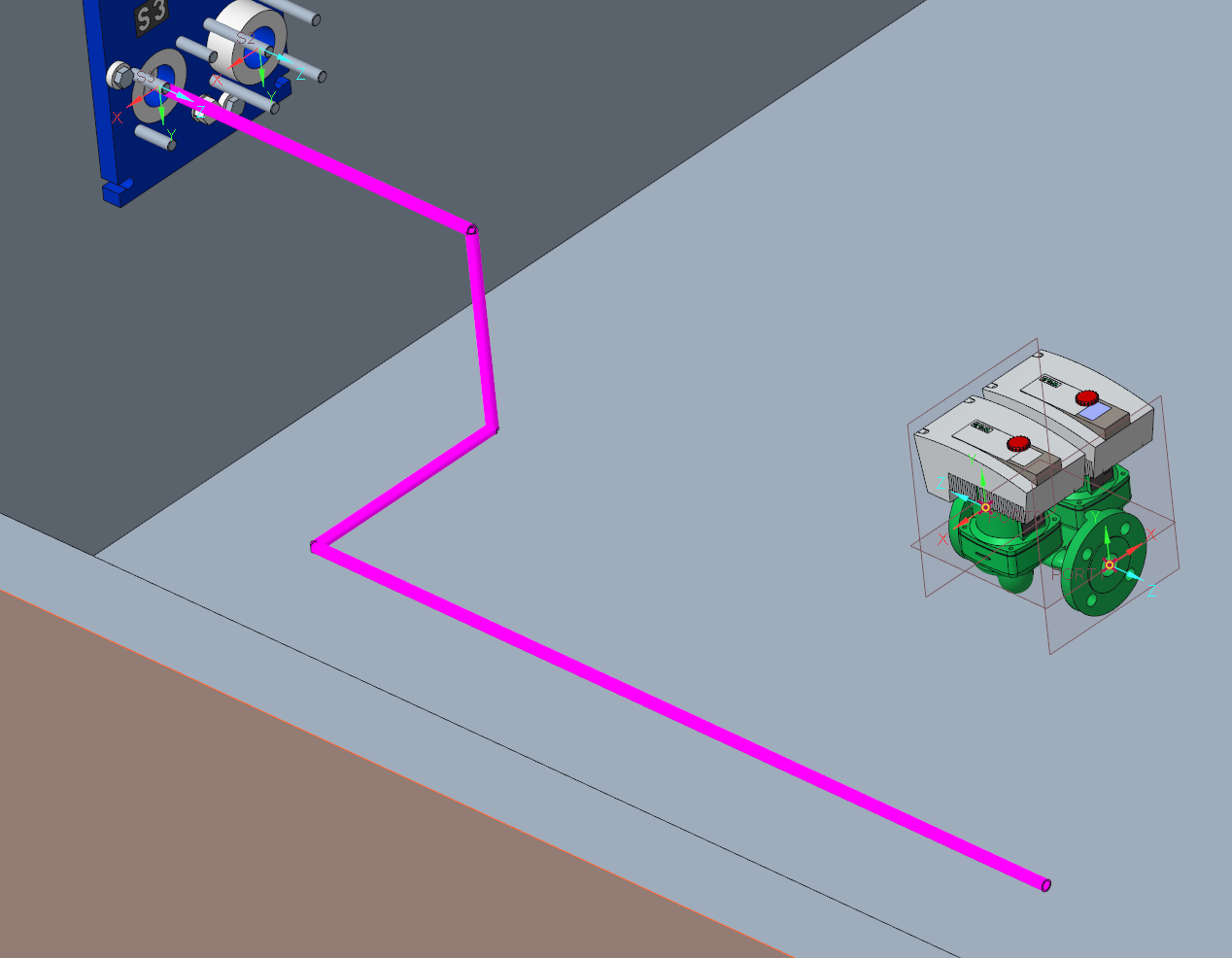
Example solid pipeline created using PTC's sample Steam specification. The pipe size, schedule, appearance, and bend information are driven by the configured piping data.
Why Use Spec-Driven Piping?
The primary benefit of Spec-Driven Piping is standardization.
A company can configure its approved piping data once and then allow designers to build systems using those predefined standards. This can help:
Limit designers to approved pipe and fitting selections
Maintain consistent sizes, materials, schedules, and end types
Automatically filter fitting selections based on the active piping specification
Apply standardized bend and piping design information
Maintain reusable company piping standards
Support reporting, drawings, and downstream piping information
For example, when inserting a fitting, Creo can use the active specification and catalog data to determine which components are compatible with the selected pipe size, schedule or rating, and end type.
Rather than each designer independently deciding how a piping system should be defined, the standards are maintained centrally in the Spec-Driven Piping data.
How Spec-Driven Piping Works
At a high level, Spec-Driven Piping connects your company's configured piping data with the Creo model.
The general workflow can be thought of as:
Master Catalog & Fitting Libraries
↓
Project Piping Specifications
↓
Designer Selects a Specification, Size, Schedule, and Other Pipeline Information
↓
Creo Uses Those Selections While Routing and Inserting Fittings
When creating a pipeline, the designer does not need to manually define all of the piping information from scratch. Instead, Creo presents choices based on the configured Spec-Driven Piping database.
For example, the designer can select:
Specification — The piping specification being used
Size — The nominal pipe size
Schedule — The pipe schedule or wall-thickness designation
Mnemonic — A descriptive identifier associated with the specification
Pipeline Number — An identifier for the individual pipeline
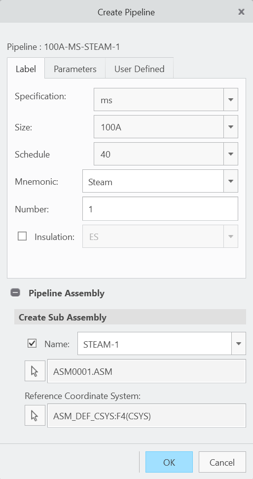
Example of creating a pipeline using PTC's sample Steam specification with a 100A size and Schedule 40 pipe.
In the example above, the designer has selected the ms piping specification. Creo then uses the associated project and catalog data to define the available pipeline selections and create the pipeline using those standards.
The Pipeline Assembly section can also be used to create or identify the subassembly that will contain the new pipeline and establish its reference coordinate system.
Once the pipeline has been created, the designer can begin routing it through the assembly. Creo continues to reference the active specification when determining the appropriate piping information and which components are available.
This means that two designers using the same specification are working from the same controlled set of piping data rather than independently defining their own pipe and fitting information.
The Spec-Driven Piping Database
The Spec-Driven Piping environment is built around several related types of data. Together, these files determine which piping specifications are available, which components can be selected, and which Creo models are ultimately placed into the assembly.
Master Catalog (MCAT)
The Master Catalog contains the detailed piping data that can be used by Creo. This includes information for items such as:
Pipes
Fittings
Insulation
Bends and miters
Materials
Sizes and compatibility information
Think of the Master Catalog as the larger collection of piping data available to your organization.
Project Data
Project Data determines which portions of the larger Master Catalog are made available for a particular piping project or specification.
This includes information such as:
Available piping specifications
Specification mnemonics
Colors and layers
Auto-selection files
Pipes and fittings assigned to each specification
Insulation selections
When a designer selects a specification, Creo uses this project data to determine which piping options should be presented.
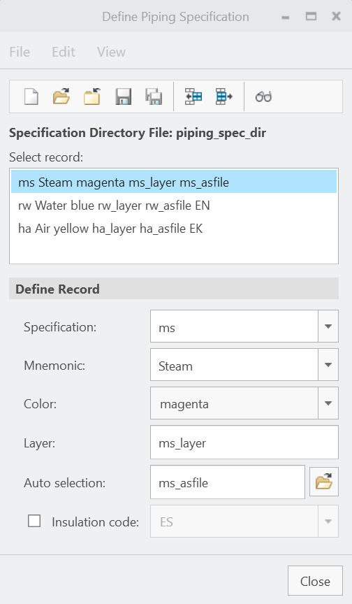
Example PTC sample piping specifications showing predefined specification, mnemonic, color, layer, and auto-selection data.
In the example above, the Steam specification is associated with its own mnemonic, display color, layer, and auto-selection file. The auto-selection file is then used to control which piping components and sizes are available when that specification is used.
Fitting Library
The Fitting Library contains the actual Creo models used for components such as elbows, tees, reducers, valves, flanges, and other fittings.
The catalog and project data tell Creo which fitting is appropriate and available, while the Fitting Library provides the actual Creo part or assembly that gets inserted into the piping model.
A useful way to think about it:
The Master Catalog contains what could be used, the Project Data controls what should be available for a specification, and the Fitting Library contains the actual Creo models that get placed.
Example PTC sample piping specifications showing predefined specification, mnemonic, color, layer, and auto-selection data.
In the example above, the Steam specification is associated with its own mnemonic, display color, layer, and auto-selection file. The auto-selection file is then used to control which piping components and sizes are available when that specification is used.
Fitting Library
The Fitting Library contains the actual Creo models used for components such as elbows, tees, reducers, valves, flanges, and other fittings.
The catalog and project data tell Creo which fitting is appropriate and available, while the Fitting Library provides the actual Creo part or assembly that gets inserted into the piping model.
A useful way to think about it:
The Master Catalog contains what could be used, the Project Data controls what should be available for a specification, and the Fitting Library contains the actual Creo models that get placed.
A Typical Spec-Driven Workflow
Once the piping environment has been configured, a typical designer workflow is:
Open or create a piping assembly.
Open Applications → Piping and work in Spec-Driven mode.
Create a pipeline and select the required specification, size, schedule, and other pipeline information.
Define the starting location of the pipeline.
Route the pipeline through the assembly.
Create pipe bends or insert fittings as required by the design.
Generate the solid pipe geometry.
Continue modifying, validating, reporting, and documenting the piping system as required.
Creo references the active piping specification throughout this process.
For example, bend information can be derived from the configured piping data, while inserted fittings can be filtered based on the active specification, size, schedule, and compatibility requirements.
This allows the designer to focus on the piping layout while Creo uses the centrally configured data to help maintain the organization's piping standards.
Pipe Bends and Fittings
Pipe bends and fittings are related, but they are not necessarily the same thing in Creo Piping.
A pipe bend can be created directly as part of the routed pipeline. Creo uses the configured bend information to generate the curved portion of the pipe when the solid geometry is created.
A separate fitting, such as an elbow, tee, flange, valve, or reducer, is an individual Creo component inserted into the pipeline from the configured fitting library.
Which method is appropriate depends on the piping specification and the requirements of the design.
This distinction is important when configuring company piping standards because both the piping data and fitting libraries contribute to the final piping system.
Spec-Driven vs. Non-Spec-Driven Piping
Creo also supports Non-Spec-Driven Piping.
With Non-Spec-Driven Piping, the designer works more directly with line stock and pipeline parameters. It does not use the same project-specific specification database or provide the same level of specification-controlled component selection.
With Spec-Driven Piping, piping standards can be centrally configured so that designers work from predefined specifications and libraries.
For organizations that maintain defined piping standards, Spec-Driven Piping provides a more structured environment because the available design choices can be controlled through centrally managed data.
Sample Piping Data Included With Creo
Creo includes sample Spec-Driven Piping data that can be extremely useful when learning how the system works or when developing company-specific piping standards.
The sample data includes examples of:
Master Catalog data
Piping specifications
Auto-selection files
Fitting libraries
Materials
Sizes and schedules
Bend information
Insulation data
Other project configuration files
The screenshots in this article use PTC's supplied sample Steam specification.
For a typical Creo installation, the sample piping data can be found beneath a location similar to:
<Creo Load Point>\Common Files\text\piping_data
Common subfolders include:
master_catalog
sample_project
fittinglib
These examples are useful for understanding how PTC expects the different Spec-Driven Piping files to relate to one another before building an organization-specific library.
Tip: Use the PTC sample content as a reference rather than directly modifying the installed sample files. For a production environment, company-managed piping data should generally be maintained in a separate controlled location.
For more information about other sample libraries and templates included with Creo, see:
[Initial Creo Configs + Starting Templates]
Additional PTC Documentation
PTC's Creo Help Center contains detailed documentation for configuring and using Spec-Driven Piping.
PTC Help – Spec-Driven Piping Overview
PTC Help – Setting Up Spec-Driven Piping
These resources cover more detailed configuration and modeling workflows, including specification databases, routing, fitting placement, design rules, fabrication, drawings, and reporting.